")
")
Measurement of parameters and display on a remote device. For example, system statuses can be displayed on remote control panels or measured values from Digalox devices can be accessed by third-party devices.
The product versions DPM72-MPN+, DPM72-MP+, DPM72-MPP, DPM72-MPPA and DPM72-MPPV are available as Modbus variants. These devices can be used in slave or master mode. Depending on the cable length and topology, up to 32 devices can be connected. The connection of third-party devices is also possible; there are extensive options for adapting the data transmission.
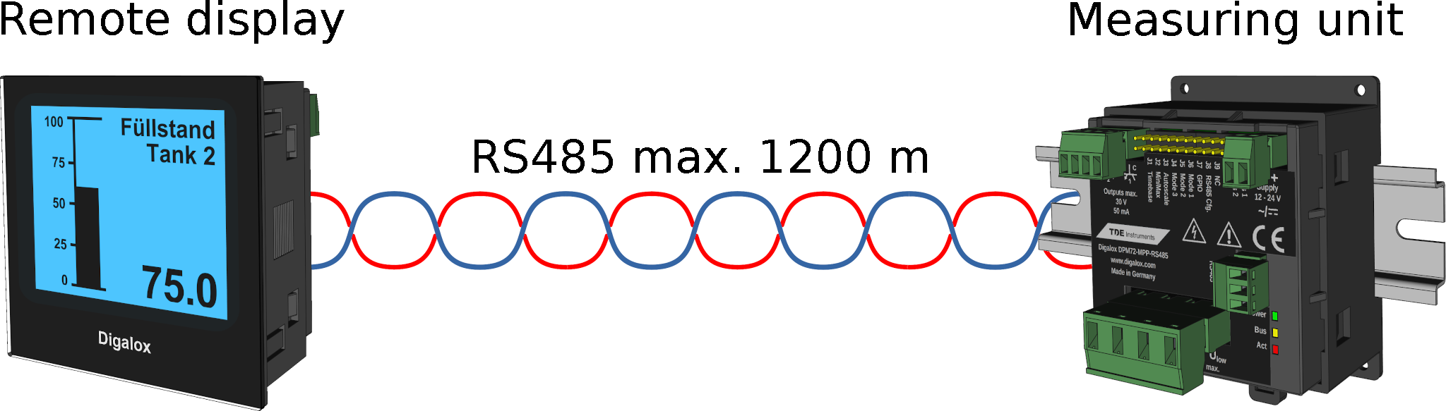
The following application example describes the connection of a measuring unit with a display unit. The display unit acts as a Modbus master, which reads out the measured values from the measuring unit at regular intervals.
Wiring
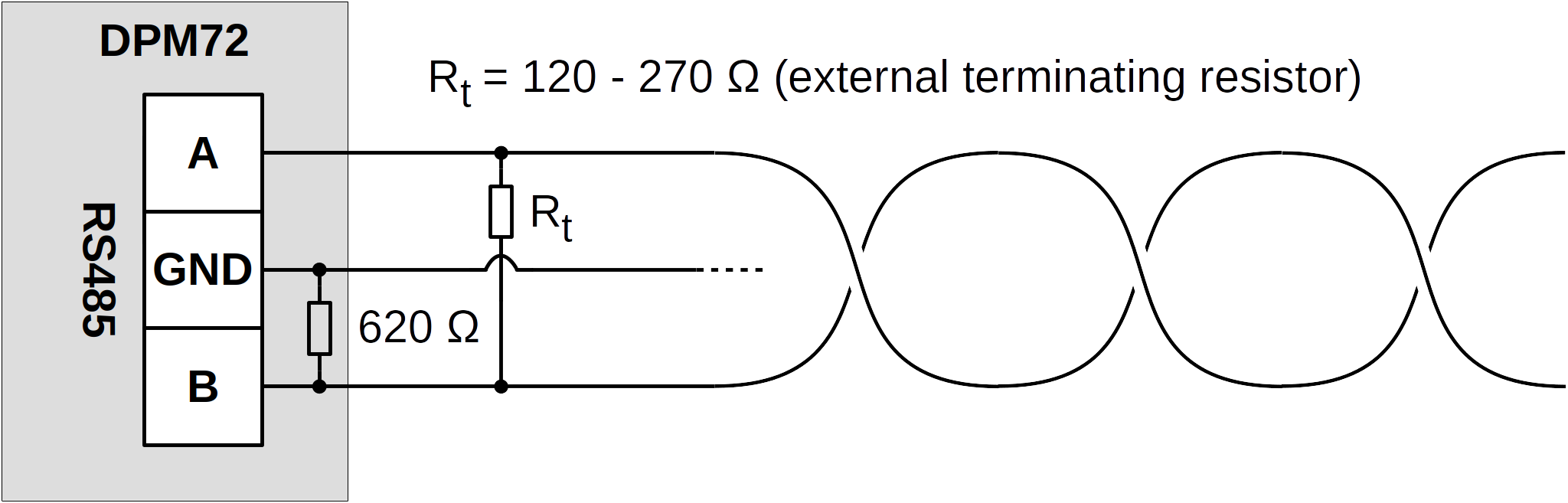
The devices are connected ideally via a twisted cable, optionally the ground can be carried along. The ground of the RS485 connection is internally connected to the ground of the device supply. The main circuit and measuring input of the devices are internally galvanically separated from the supply and the RS485 connection. There is an internal resistance of 620 ohms between channel "B" and ground. Depending on the cable length and network topology, an external terminator must be attached. This is usually in the range of 120-270 ohms.
Configuration via Digalox® Manager
The devices are configured using the Digalox® Manager software, which is available free of charge. To do this, the configuration mode is activated on the respective device and then connected to a PC via an RS485 USB adapter. The basic Modbus settings such as baud rate, parity and number of stop bits can be set there.
Configuration of measuring unit as slave
The slave mode is activated on the measuring unit and a unique slave ID is set. In addition, the measurement-relevant parameters such as measurement type (volt/ampere, AC/DC) and scaling are set here. Up to four parameters can be configured, which are then available via the interface.
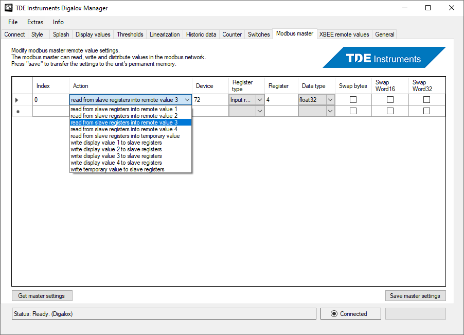
Configuration of display unit as master
The master mode is activated on the display unit. The device takes on the role of the Modbus RTU master and thus has control over the entire communication in the Modbus network. Communication is configured using a list with a maximum of 64 individual entries. Basically, values can be read or written. Input registers or holding registers with 16, 32 or 64 bits can be accessed and, in addition, floating point numbers with 32 bits. For the connection of third-party devices, it is possible to adjust the byte order for each step. When using two Digalox® devices, usually 32-bit floating point numbers are used. The measured value read by the slave must be assigned to a display value. This display value can also be scaled and provided with threshold values.
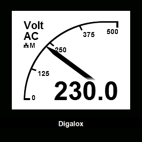
After removing jumper J8, the device changes to Modbus mode and starts communication. The symbols in the display provide information about the current state of the data transmission. The symbol "M" stands for master and "S" for slave. In addition, there are 3 LEDs on the rear of the device, which indicate bus activity and transmission activity.