")
")
Measurement of parameters and display on a remote device. For example, systems located outside can be monitored without laying cables.
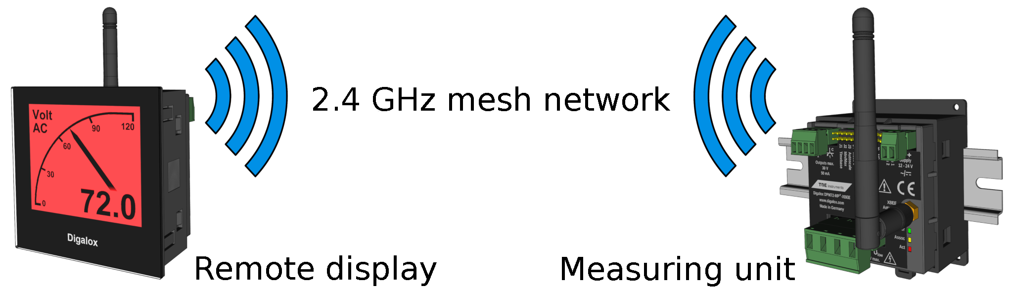
The product versions DPM72-MPN+, DPM72-MP+, DPM72-MPP, DPM72-MPPA and DPM72-MPPV are available as XBEE variants. These devices have an internal XBEE3 module and a detachable SMA antenna. The devices connect to each other via the 2.4 GHz mesh network. The basic range between two points corresponds to the range of 2.4 GHz WiFi networks. Thanks to the special mesh topology, each device acts as a radio transmitter and extends the range by a distance. In this way, for instance, entire complexes of buildings can be linked in a chain.
The following application example describes the connection of a measuring unit with a display unit. The display unit functions as an active device, which reads out the measured values from the measuring unit at regular intervals.
Installation
The devices are mounted in such a way that the antenna can form a radio link as free as possible to the next radio node. If possible, metal housings and plates should not be present between the antennas. In order to optimize the position of the antenna, an antenna extension cable can be attached to the SMA connector and the antenna be mounted e.g. on the outside of a control cabinet. Long distances or the bypassing of metallic interferers such as control cabinets or steel doors can be optimized by adding additional radio nodes or XBEE repeaters.
Configuration via Digalox® Manager
The devices are configured using the Digalox® Manager software, which is available free of charge. To do this, the devices are connected to a PC via the Digalox-XBEE-USB adapter. The basic XBEE network settings (network ID and key) can be configured there as well as a role. One device must be the coordinator who establishes and manages the XBEE network. The other devices have to be configured as routers.
Configuration of measuring unit
The measurement-relevant parameters such as measurement type (volt/ampere, AC/DC) and scaling are set on the measuring unit. Up to four parameters can be configured, which are then available via the interface.
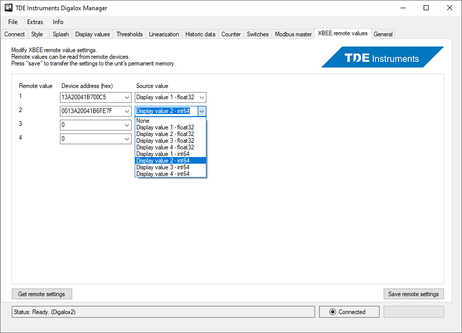
Configuration of display unit
The measured values to be retrieved from the measuring unit are set in the display unit and assigned to a display value. This display value can also be scaled and provided with threshold values.
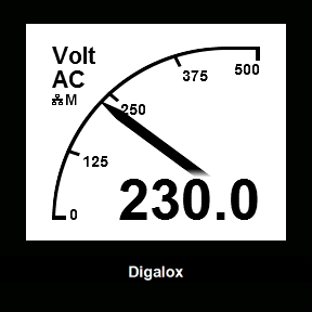
As soon as the network ID and key have been changed so that they no longer correspond to the default settings, the device starts measuring. The symbols in the display provide information about the current state of the data transmission. The symbol "M" stands for master and "S" for slave. In addition, there are 3 LEDs on the rear of the device, which indicate the connection status and transmission activity.